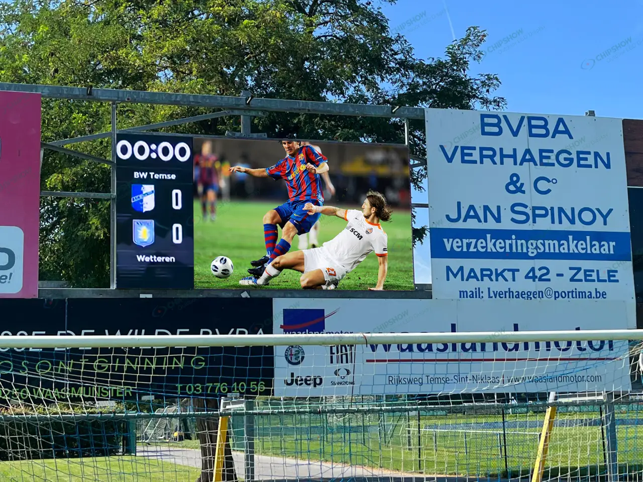
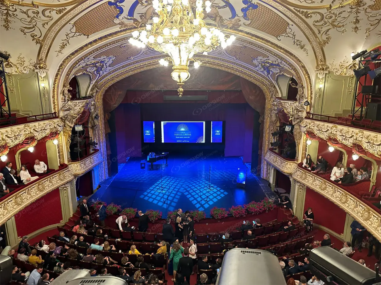
An outdoor LED display requires project-specific structural design. Manufacturer drawings provide equipment dimensions and mounting interfaces; they cannot replace site wind calculations or foundation checks. The manufacturer supplies verified equipment data, while a locally qualified structural engineer handles site-specific calculations and structural design approval within the appointed scope. Coordinating these inputs early helps prevent connection conflicts, fabrication changes, and permit delays.
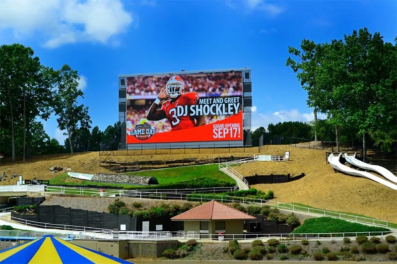
Define Structural Responsibilities Before Design Begins
Assign responsibility for each document, calculation, and interface at the procurement stage.
An outdoor LED display connects equipment, supporting steelwork, building elements, and foundations. The contract should identify who designs each part and who coordinates the complete load path.
Manufacturer Equipment Data
The LED manufacturer should supply configuration-specific drawings covering dimensions, cabinet weights, attachment points, and service requirements. Each drawing should carry a revision number and issue date so all parties use the same equipment data.
The package should identify permitted support arrangements and available connection-capacity data. Equipment wind-resistance claims should include supporting evidence for the tested or calculated configuration and its boundary conditions.
The structural engineer uses these equipment ratings alongside project-specific calculations to verify the complete outdoor LED display installation.
Engineer Calculations and Approval
The project structural engineer establishes the design basis and evaluates the load path through the supports, connections, and foundations. The assessment should address strength, stability, serviceability, and applicable load combinations.
Define any delegated design for subframes, brackets, or specialist connections. Each delegated designer needs documented loads, geometry, interface requirements, and review responsibilities.
The architect coordinates building geometry, facade details, waterproofing, and access. The responsible engineer approves the structural design within their scope; the relevant authority provides regulatory approval where required.
Contractor Installation Details
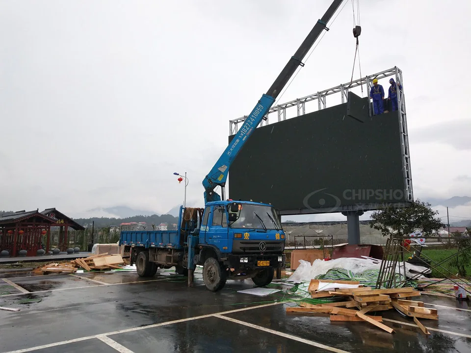
The general contractor coordinates surveys, trade interfaces, fabrication submissions, and installation sequencing. The installer submits fixing methods, lifting arrangements, and field details within its contracted scope.
Assign temporary works design explicitly. Permanent calculations may assume a completed frame that remains incomplete during erection.
Require documented engineering review of substitutions, relocated anchors, and field changes affecting the approved design. Identify who records the final installed condition.
Collect Site Data for Wind Load Calculations
A reliable wind design basis combines the project location with the actual installation conditions.
An LED display wind load calculation requires site-specific wind speed, exposure, installation height, and display geometry. Document these inputs and the applicable design assumptions for the structural engineer’s assessment.
Location and Adopted Code
Record the site address, coordinates, governing jurisdiction, adopted code edition, and local amendments. Ask the engineer to document the design wind speed and applicable risk or reliability classification.
Record the wind-speed definition, including its averaging period and reference conditions. Numerical speeds from different standards may represent different design conditions and cannot automatically be compared.
The design basis should also identify other applicable actions, including seismic, snow, ice, and temperature effects. The engineer determines the governing combinations.
Wind Exposure and Installation Height
Document the display’s height, orientation, depth, and position relative to building edges. Include elevations and photographs showing surrounding buildings, open land, water, hills, and escarpments.
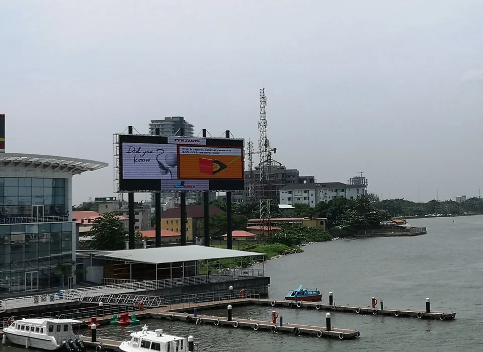
The engineer determines the applicable exposure or terrain category and topographic effects. The engineer assesses how surrounding buildings affect wind exposure using the applicable code provisions and site conditions.
A rooftop outdoor LED display also interacts with its host building. Roof-edge position, local airflow, support flexibility, and building response can affect the assessment.
Show gaps behind the screen, rear enclosures, and adjacent architectural features. These details help the engineer select an appropriate wind-loading model.
Existing Structure and Foundation
For retrofits, collect available structural drawings, previous calculations, foundation records, and geotechnical information. Arrange a condition survey to compare those records with the installed structure.
The engineer should identify missing evidence and specify investigations. Depending on the project, these may include material testing, anchor verification, foundation exposure, or ground investigation.
Existing capacity for an older sign does not establish capacity for a replacement outdoor LED display. Changed dimensions, weight distribution, eccentricity, and connection positions can alter structural demand.
Convert Display Data Into Structural Loads
Convert the selected equipment configuration into traceable loads at defined support locations.
A complete outdoor LED display structural design needs both manufacturer inputs and engineering calculations. Keep equipment data distinguishable from calculated design actions.
Dead Load and Center of Gravity
Provide cabinet quantities and masses, together with subframes, electrical equipment, rear covers, and permanent accessories. State which components each supplied figure includes.
Distinguish mass, commonly supplied in kilograms, from structural force, expressed in newtons or kilonewtons. Maintain consistent units throughout the load schedule.
Locate the center of gravity relative to the support plane. An offset introduces moments that must transfer through brackets, connections, and supporting members.
Total outdoor LED display weight is insufficient for connection design. The engineer also needs its distribution, attachment geometry, and the supporting system’s stiffness.
Projected Area and Porosity
Provide the overall screen envelope, solid surfaces, openings, cabinet depth, and rear cladding. Include exposed support members and accessories where relevant.
An open-area percentage does not establish an equal percentage reduction in wind load. Visual transparency, geometric porosity, and aerodynamic behavior describe different properties.
The engineer must assess the complete assembly using an applicable calculation method or suitable substantiated test data. Rear covers, cable trays, and finishes can change airflow through a ventilated screen.
For projects considering a wind resistant LED billboard, Chipshow’s C-Vent P16 offers a ventilated hollow-cabinet configuration. Its geometry provides equipment input for engineering assessment; the installed system still requires site-specific wind and structural verification.
Request supporting aerodynamic evidence if the design relies on a claimed load reduction. Confirm that the evidence represents the proposed assembly.

Maintenance and Cable Loads
Include service platforms, walkways, ladders, guardrails, cable trays, and permanent equipment. Establish maintenance personnel, tools, and temporary equipment loads with the engineer.
Show where each load enters the structure. A rear platform can introduce eccentric loading beyond the screen’s own weight.
Coordinate cable supports and movement allowances. Cables should remain clear of component-removal paths and accommodate the movement specified by the designers.
The outdoor LED display load schedule should reference the equipment drawing revision behind every input. Update it whenever the selected configuration changes.
Coordinate Mounting, Access, and Movement
Resolve equipment and structural interfaces while changes remain practical.
The LED screen mounting structure must transfer loads reliably while supporting accurate assembly, maintenance access, and environmental movement.
Connection and Anchor Locations
Use a shared coordinate system for cabinet attachment points, support rails, steelwork, baseplates, and anchors. Dimension these locations from agreed datums.
Document the information required at each interface:
| Interface | Required Coordination | Design Responsibility to Assign |
|---|---|---|
| Cabinet to support rail | Confirm attachment geometry, fixing arrangement, and available capacity data. | Assign equipment-interface and connection design. |
| Rail to primary frame | Define reactions, eccentricities, stiffness assumptions, and connection details. | Assign supporting-frame and connection design. |
| Frame to building or base | Establish anchor actions, layout, substrate conditions, and installation requirements. | Assign anchorage and supporting-element checks. |
| Foundation to ground | Establish bearing, sliding, overturning, uplift, and settlement requirements. | Assign structural and geotechnical design inputs. |
The contractual assignments should cover the complete load path. Assign responsibility for verifying every connection along the load path, from cabinet attachments through building anchors to foundations.
An LED billboard steel structure drawing should specify members, connections, fasteners, welds, and corrosion protection as required by the designer. Anchor details also need substrate assumptions, installation requirements, and inspection provisions.
Flatness and Installation Tolerances
Agree tolerances for fabricated steelwork, erected supports, mounting rails, and cabinet alignment. Coordinate the supporting frame with the manufacturer’s equipment requirements.
Installation tolerance and structural deflection describe different conditions. A frame can meet erection tolerances yet move excessively under service loads.
Ask the engineer and manufacturer to coordinate allowable movement at the equipment interfaces. Consider cabinet fit, visible alignment, and connection behavior.
Show permitted adjustment methods and limits on the drawings. Slotted holes, shims, and adjustable brackets need designed fixing details and defined movement functions.
Service and Drainage Clearance
Verify the actual module and cabinet removal paths. Front-service equipment still needs working space, access equipment, and unobstructed component handling.
Coordinate rear access with bracing, cable trays, electrical enclosures, and platforms. Confirm that personnel can reach the specified fixings after assembly.
Provide drainage paths and coordinate roof or facade penetrations with the building-envelope designer. Detail connections to limit water retention and allow inspection.
The outdoor LED display assembly should accommodate specified thermal movement. Identify fixed and sliding interfaces where required, and keep finishes clear of movement gaps.
Include these requirements in the erection sequence so later work does not obstruct access or drainage.
Review the Complete Drawing Package
Review calculations, equipment data, and installation details as a coordinated submission.
Confirm the governing structural codes, adopted editions, and local amendments for the project location. Record the applicable wind-loading provisions and national or regional parameters in the design basis.
Relevant references may include ASCE 7-22 or EN 1991-1-4 with its applicable National Annex. The structural engineer should confirm which standards and editions govern the project.
The submission should include the design basis, calculations, general arrangement, member details, connections, anchors, foundations, and equipment interfaces. Include temporary works and erection requirements within their assigned scope.
Check that outdoor LED display dimensions, masses, and attachment locations match across all documents. Confirm that connection and foundation designers receive consistent reactions and loading conventions.
Maintain a revision register showing each change, its origin, and its engineering disposition. Equipment substitutions, added cladding, altered gaps, and relocated supports can change earlier assumptions.
Release fabrication after resolving comments affecting safety, fit, and load transfer. Distribute the approved revisions to the manufacturer, fabricator, contractor, and installer.
Coordinated Drawings Support Outdoor LED Display Fabrication
Structural drawings are ready for release once design responsibilities, site conditions, equipment loads, connections, and access requirements are confirmed. Chipshow can review the structural package, wind design parameters, and selected outdoor LED display configuration for equipment-interface coordination. The appointed qualified engineer remains responsible for site-specific structural calculations and design approval within the agreed scope. Documented revisions and required approvals provide a coordinated basis for fabrication.
FAQs
Q1. Does a Rooftop Outdoor LED Display Need a Vibration Review?
The structural engineer should assess the need. Slender supports, flexible roofs, cyclic wind response, and sensitive building uses can justify further analysis. Equipment mass alone cannot establish acceptable vibration performance for the complete installation.
Q2. When Is an Independent Structural Peer Review Required?
Requirements depend on the jurisdiction, approving authority, owner, and contract. Confirm them during project planning. Unusual geometry, complex structural behavior, or high-consequence installations may trigger an independent review requirement.
Q3. Should Foundation Conditions Be Tested Before Design?
The engineer should define investigations during design development. Missing records, uncertain ground conditions, deterioration, or increased loading may require testing. Resolve assumptions affecting foundation capacity ahead of construction release.
Q4. How Are Temporary Construction Loads Included?
Assign erection-stage engineering and document the sequence. Assess lifting, incomplete frames, temporary bracing, stored materials, and construction-stage wind. Record applicable operating limits and hold points in the erection plan.
Q5. Can an Outdoor LED Display Be Enlarged Without Recalculating the Structure?
Any enlargement requires engineering review. Increased area, mass, height, or eccentricity can change wind demand and foundation reactions. The engineer determines the necessary recalculation, connection changes, and strengthening.