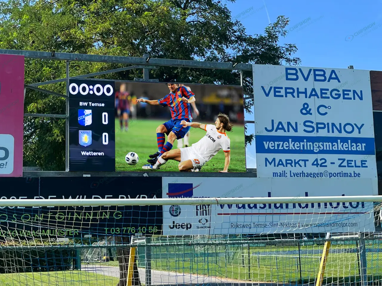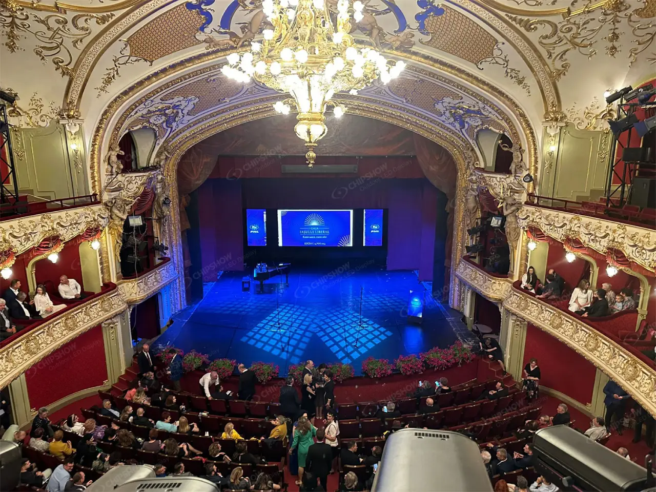


No single wind rating on an outdoor LED display cabinet can approve a high-rise or roadside installation. Wind load planning is a site-specific structural process where an engineer must establish the project design basis, trace the load path to the ground or host structure, and confirm permit approvals before equipment procurement.
If any of those elements is missing, the project remains conditional. The following sections walk through the inputs to gather, the complete load path to trace, the cabinet documents to request from a supplier, and the permit and installation handoff steps required for compliance.
Start With a Site-Specific Wind Design Basis
A generic outdoor LED display wind statement is never a site approval. Wind actions on a display depend on project elevation, local terrain, and specific structural attachments, creating distinct requirements for identical hardware placed across different locations.
Why a generic wind rating is not a site approval
Wind pressures and structural requirements escalate with building height, exposure category, and local terrain roughness. While supplier cabinet documentation details useful equipment data such as dimensions or frame ventilation, it cannot replace project-specific wind calculations prepared by a qualified structural engineer. In the United States, the ASCE 7 wind provisions adopted by local building codes govern how buildings, structures, and externally attached equipment must be designed.
The procurement hold point
Procurement and field installation should pause until a qualified professional confirms the site-specific wind design basis, the complete structural load path, and all approval ownership. Assembling site inputs, tracing the load path, reviewing supplier documentation, resolving permit demands, and coordinating site safety establish that structural threshold.

Build the Wind-Load Site Feasibility Checklist
Before initiating an engineering review, integrators should assemble a comprehensive input package covering site exposure, display dimensions, support conditions, and approval authorities. Missing items must remain flagged as open items rather than populated with assumed values.
- Site and exposure: project address, building height or ground elevation, surrounding terrain roughness (urban, coastal, open), and display placement on the host structure.
- Display geometry and dead load: overall display dimensions, orientation, parapet or roof edge setbacks, total projected area, cabinet dead load, and service access doors.
- Support and attachment: structural type (curtain wall, parapet, structural roof deck, monopole, billboard framework), structural material conditions, and existing inspection records.
- Access and temporary conditions: crane or boom lift staging, pedestrian protection requirements, and tenant occupancy during installation.
- Approvals and document ownership: the authority having jurisdiction (AHJ), required permit classes, and defined roles for the engineer, supplier, owner, and installer.
Any parameter left blank constitutes an unresolved action item that the engineer or supplier must address before finalizing the design package.
Evaluate the Complete Structural Load Path
The structural engineer must evaluate the entire structural load path rather than analyzing the outdoor LED display cabinet in isolation. This engineering evaluation branches into two distinct structural scenarios based on mounting geometry.
Façade and rooftop attachment
For building-mounted equipment, the engineer traces loads through the display modules, mounting subframe, mechanical anchors, and parapet or façade connections directly into primary structural framing. Reviewing equipment-to-structure attachment adequacy is critical because high-wind rooftop failures typically stem from inadequate anchorage, insufficient equipment casing strength, or advanced fastener corrosion rather than cabinet face performance alone.
Roadside and freestanding support
For roadside billboards or freestanding signs without an existing building substrate, the structural load path shifts to the dedicated support frame, tubular column or monopole, and poured concrete foundation. Using a ventilated or lightweight cabinet reduces applied wind drag but does not eliminate the necessity of sizing structural steelwork and foundation embedments to match local wind exposure.
Request Cabinet and Mounting Documentation Before Procurement
Before issuing purchase orders, integrators must secure specific cabinet and interface documentation from the display manufacturer, treating technical product specifications as engineering submittal inputs rather than regulatory approvals.
Documents to request from the supplier
- Dimensional drawings: cabinet dimensions, overall frame depth, and module junction spacing for mounting frame fabrication.
- Dead load and projected area: cabinet weight per unit area and gross projected surface area for gravity and wind pressure calculations.
- Attachment points and mounting interface: cabinet anchor bracket locations, bolt shear capacities, and interface tolerances.
- Service method: front-service versus rear-service access layouts to verify structural clearance and technician safety.
- Certifications: electrical, environmental, and material documentation, such as ETL or CE records, confirming standard product compliance.
- Available engineering drawings: manufacturer-issued structural interface drawings and connection point schematics.
Match cabinet concepts to the installation scene
Our C-Vent P16 record details a hollow, ventilated cabinet structure designed to mitigate wind resistance across the panel body, utilizing 960 × 960 mm panels with a 90 mm depth and IP65 protection. It serves as a candidate for roadside billboards, rooftops, or monopoles subject to structural verification. Integrators can review our C-Vent P16 billboard specifications as an initial design submittal package.

Where installations involve open highway gantries, toll plazas, or bridges, our C-Tra-Vent Mesh VMS documentation specifies a ventilated mesh design featuring at least 35% air permeability and a weight profile of approximately 27 to 30 kg/m² to reduce solid surface wind resistance. These parameters function as inputs for aerodynamic calculations rather than universal wind allowances; review our C-Tra-Vent Mesh VMS documentation for technical details.
For retail façades and high-profile visual landmarks requiring conventional surface profiles, our Outdoor DOOH video wall solution provides an ultra-slim, wind-load-optimized enclosure with ETL and CE certifications. Submit these manufacturer specifications directly to the engineer of record to verify site-specific load capacity.
Confirm Permits, Code, and Work-Scope Requirements
Permit compliance cannot be established through national standard references alone; the installation team must confirm local jurisdictional requirements and classify physical construction tasks prior to scheduling field crews.
Questions for the AHJ and project engineer
- Which locally adopted editions of building, structural, sign, and electrical codes govern the site, and which ASCE 7 edition do they enforce?
- What signed and sealed structural calculation packages, wind pressure evaluations, or special inspection reports are required for permit issuance?
- Does mounting to a designated façade, parapet, or existing steel support change the structure’s classification or necessitate supplemental structural reinforcing?
Confirming these submittal requirements directly with the local AHJ prevents incomplete applications and permitting delays.
Classify the actual installation work
The installation team must outline the exact tasks scheduled on site to determine regulatory oversight. When personnel execute on-site structural member construction or erect dedicated billboard frames, OSHA applies construction standards rather than general industry standards. Confirming the work scope early ensures correct safety planning and qualified fall-protection implementation.
Plan High-Rise Installation, Inspection, and Handoff
Once engineering calculations, building permits, and manufacturer submittals receive formal sign-off, project teams must transition focus to field coordination, rigging sequences, code inspections, and closeout records.

Sequence the work before crews arrive
- Verify stamped engineering calculations, approved permits, and building owner access authorizations are on file prior to mobilization.
- Coordinate mobile crane staging, street closure permits, drop zones, and pedestrian protection corridors.
- Establish temporary shoring or tie-back procedures during panel assembly, identifying who signs off on interim structural states.
- Establish site-specific weather limits, designating explicit wind speed cutoffs that pause hoisting operations.
- Review crew certifications and confirm whether the project involves on-site fabrication of structural framing, ensuring compliance with construction standards.
Inspect, document, and hand off
Assigned inspectors must examine anchor torques, weld integrity, and frame plumbness against approved engineering plans during installation. Field personnel must document as-built conditions, logging any anchor modifications, electrical feed variations, and service clearances. The completed project record delivered to the asset owner should combine stamped structural calculations, building permits, signed inspection logs, and manufacturer submittals to ensure full operational compliance.
If you have assembled your site parameters, contact our technical team to match our certified cabinet documentation and structural drawings with your project engineer’s submittal package.
FAQs
Can an existing billboard frame or rooftop attachment be reused for a new LED display?
Reuse is possible only after a licensed structural engineer re-evaluates the existing support framework against the new display dead load, updated wind action calculations, and actual connection geometries. Integrators must furnish original structural drawings, recent non-destructive inspection reports, steel corrosion assessments, and the new display interface drawings so the engineer can issue a formal retrofit determination prior to procurement.
What technical documentation must an LED display manufacturer supply for structural permit review?
For a structural permit review, the manufacturer must provide detailed dimensional drawings, exact cabinet and module dead loads, gross solid projected face area, mechanical anchor interface points, and material safety certifications. In addition, if the display utilizes a ventilated or mesh enclosure to reduce wind drag, the manufacturer must provide verified permeability data and structural interface drawings so the engineer of record can determine the appropriate aerodynamic force coefficients.
Who is legally responsible for verifying that an outdoor LED display meets local wind codes?
The project’s licensed professional engineer of record holds legal responsibility for calculating wind actions, designing the attachment system, and stamping the structural package under the locally adopted building code and ASCE 7 standard. While the display manufacturer supplies equipment-level physical data and the contractor oversees installation compliance, the engineer of record verifies and seals the complete structural load path submitted to the AHJ for permit approval.