

LED wall redundancy is best treated as a failure-domain decision, not a promise of zero interruption. If you are buying for a command center or other mission-critical room, the first question is not whether the wall is "redundant," but what happens when a controller, cabinet, power path, or signal path fails. The right architecture depends on how much visual disruption you can tolerate, how quickly your team can test recovery, and which fault you most need to contain.
What Redundancy Has to Protect
In practice, the operator problem is simple: keep the content visible, keep control predictable, and keep recovery bounded when something breaks. That is why LED wall redundancy has to be judged by the failure domain it protects, not by the label on a brochure. A controller fault, a cabinet fault, a lost signal path, and a power-path issue do not all fail the same way, so one layer rarely covers everything.
A useful rule of thumb is this: if the failure can blank the whole wall, you need system-level protection; if it only affects one cabinet or one input chain, local protection may be enough. The failure isolation across segments idea is a helpful planning model here, because it shows why splitting responsibility can reduce the blast radius of one bad component. But it is still a model, not a guarantee that every architecture behaves the same way.
For buyers, the practical decision sentence is this: if you cannot clearly say what stays on-screen during a fault, the redundancy story is not finished yet. That is the difference between an architecture and a marketing claim. It also explains why the rest of this article separates controller, hot spare, signal-path, and cabinet-level protection instead of treating them as one feature.
Dual-Controller Failover Basics
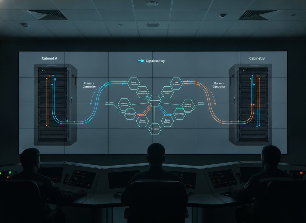
Dual-controller LED wall failover is the layer most operators think of first, because it protects the processor or controller path that feeds the wall. NovaStar’s automatic controller hot backup failover documentation says dual-system hot backup can switch controllers, fiber, and Ethernet when the primary controller fails, which means the standby path is not just installed, it is meant to take over.
What matters for buyers is the handoff behavior. In a healthy setup, one controller is active and the other is ready with synchronized state. When the primary fails, the backup path takes over routing and control. The operator takeaway is conditional rather than absolute: the wall is designed to reduce interruption, but the visible result depends on synchronization, configuration, and how the processor detects the fault.
Primary and Secondary Controller Roles
Think of the primary controller as the active brain and the secondary controller as the ready spare. The spare only helps if it is actually synchronized, because an idle box with a cable plugged in is not the same thing as a usable backup. The hot backup model in NovaStar’s inactive synchronized standby description matches that idea: the backup stays ready but does not take over until the primary stops outputting signals.
That is the first decision sentence in this section: if your room cannot tolerate a long reconfiguration pause, you need a synchronized standby path, not a cold spare. If your room can tolerate manual recovery, simpler designs may still be acceptable, but then you should not call them seamless.
What Happens During Controller Handoff
When controller failover works as intended, the wall should keep receiving content through the backup path instead of dropping dark. In real rooms, though, operators should still plan for a possible brief visual artifact, a source switch, or a control handoff delay. The source manual supports automatic switching, not a universal promise of invisible recovery.
That boundary matters. "Dual controller" does not mean every downstream fault disappears, and it does not mean cabinet failures are solved at the controller layer. It only means the controller path has a second route if the primary path fails.
Where Dual-Controller Designs Fit Best
This architecture fits command centers that need controller-layer protection and can support configuration discipline. If the room has no staff time for testing or no clear owner for failover validation, the design can become fragile in practice even if it is technically redundant. In other words, the best fit is a team that can verify recovery, not just purchase it.
For procurement, the deciding question is whether the wall can keep operating under a controller fault without leaving the operator guessing. If the answer is unclear, the architecture needs to be specified more tightly before purchase.
Hot Spare and Signal-Path Protection
Hot spare processing and signal-path protection solve different problems. A hot spare protects the processing layer by keeping a standby device synchronized until the primary fails. Signal-path protection protects the route that carries the content, so a lost cable, input, or chain segment does not necessarily take the whole wall offline. The first helps with processor failure; the second helps with upstream link failure.
NovaStar’s loopback signal redundancy manual shows that redundancy can be configured at the port or device level, including loopback paths that keep the display running if one cable in the chain disconnects. That is a useful distinction for command center LED wall signal path protection, because a protected input path is not the same thing as a protected cabinet.
Hot Spare Processing in Practice
A hot spare is not an idle vanity box. It is a synchronized standby device that mirrors the primary state closely enough to take over when the primary stops outputting. NovaStar’s backup guidance says the spare remains inactive until the fault occurs, and that there is a hot backup verification feature for testing readiness without physically disconnecting hardware.
That testing detail is important. Redundancy that nobody validates can become a false sense of security. If your operations team cannot verify spare readiness without breaking the room, the spare is harder to trust than it looks on paper.
Signal-Path Redundancy and Input Protection
Signal-path redundancy is usually the better answer when the worry is a bad link, a disconnected cable, or an upstream path fault. The architecture can keep a wall running through a backup route, but it does not automatically protect every cabinet or every controller fault. So the practical question is not "Is there redundancy?" but "Which fault does this path actually survive?"
The decision sentence here is straightforward: if a single cable fault can black out the room, you need signal-path protection that is documented at the port or device level. If your failure concern is the processor itself, signal-path redundancy alone is not enough.
Tradeoffs: Recovery Time vs Complexity
More redundancy usually means more setup work, more configuration syncing, and more testing. That is the hidden tradeoff many procurement reviews miss. A simple design is easier to maintain, but it may leave a larger outage window. A more protected design can reduce interruption, but only if the team can validate it and keep it synchronized.
That is why the best architecture is rarely the one with the most labels. It is the one that matches your staffing, test discipline, and acceptable interruption window.
Cabinet-Level Redundancy Differences
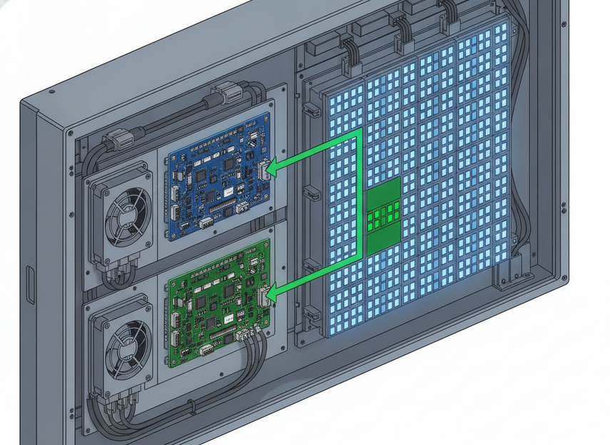
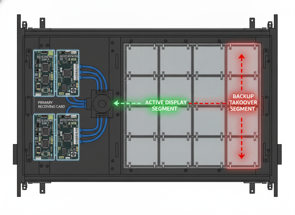
Cabinet-level redundancy protects a much smaller failure domain than controller-layer failover. NovaStar’s dual receiving-card backup guidance describes a local takeover model where the backup card can maintain the local image segment if the primary card or its signal path fails. That is valuable, but it is local protection, not whole-wall continuity.
| Redundancy layer | Failure domain protected | Visible impact scope | Does not cover |
|---|---|---|---|
| Dual-controller failover | Controller, fiber, and Ethernet path | Can protect the whole wall if the backup path is ready | Cabinet-local faults, unrelated power issues, downstream panel failures |
| Hot spare processing | Primary processor or controller layer | Usually visible at the wall level, but recovery may still show a brief handoff | Cable faults beyond the processing layer, cabinet-only failures |
| Signal-path redundancy | Input cable, chain link, or port/device route | Often limited to the affected path or chain segment | Cabinet electronics, processor failures, every downstream fault |
| Cabinet-level backup | Local receiving-card or cabinet segment | Usually limited to one cabinet or local image segment | Whole-wall controller outages, upstream network or processor faults |
The main takeaway is that cabinet protection changes the scope of the failure, not the fact of failure itself. If a cabinet fault only affects one segment, that may be acceptable in a segmented wall. If the room needs whole-wall continuity, cabinet-level backup is only one layer in a broader design.
Another practical boundary is maintenance. Local protection can make service more manageable because the fault stays isolated, but it can also create a false sense that the entire wall is covered. It is not. Controller, signal, and cabinet redundancy are separate tools, and the wrong one can leave the real failure path exposed.
How to Choose the Right Redundancy Mix
The right mix starts with the business cost of one failure. If a brief interruption is acceptable, you may not need every layer. If the room is mission-critical, the first priority is to protect the failure domain that would create the biggest operational risk. That usually means controller protection first, then signal-path protection, then cabinet-level isolation where local failures matter most.
- Define the acceptable interruption window.
- Identify the failure domain that would hurt the room most.
- Check whether the team can test and maintain the standby path.
- Confirm who owns configuration sync, spare readiness, and recovery checks.
- Ask what operators actually see when the fault occurs.
That sequence keeps the decision grounded in real operations instead of feature lists. A wall that is technically redundant but never tested is still vulnerable in practice. If your team cannot prove the handoff, the architecture is not ready for procurement signoff.
The segmentation model is useful again here: splitting responsibility across paths can reduce the blast radius of a failure, but only if the operator understands which part is isolated and which part still depends on the same upstream source. That is why command center systems should be judged by documented failover behavior, not just by redundancy language.
What Operators Should Verify Before Procurement
- Which layer fails over first, and what remains visible during the event?
- Is the standby path synchronized and ready, or only installed?
- Can the team test controller, cabinet, and signal-path fault scenarios without physically damaging the system?
- Who owns configuration sync, spare readiness, and routine validation?
- What does the operator see during the handoff, and how long is the acceptable recovery window?
If you cannot get clear answers to those questions, the redundancy architecture is still under-specified. For mission-critical rooms, that is usually the bigger risk than buying the wrong label on a spec sheet. The mission-critical wall lineup is most useful when it is paired with those acceptance checks, not used as a substitute for them.
Final Takeaway
LED wall redundancy works best when you match the layer to the failure you most want to survive. Dual-controller failover protects controller loss, hot spare processing reduces processor-side recovery risk, signal-path redundancy protects upstream links, and cabinet-level backup contains local faults. None of them automatically covers every failure domain at once. If you are building for a command center, we recommend proving the handoff, not assuming it.
FAQs
How Does Dual-Controller Failover Work in an LED Wall?
Dual-controller failover keeps a standby controller ready so it can take over if the primary controller fails. The goal is to avoid a full blackout, but the actual handoff still depends on synchronization, fault detection, and system configuration. In practice, the wall may recover quickly, yet operators should still verify what the room sees during the switch.
What Happens When a Single Cabinet Fails on a Redundant LED Wall?
With cabinet-level backup, the failure may stay limited to one local segment instead of taking down the whole wall. That is useful for containing visible impact, but it is not the same as controller failover. A cabinet fault can still leave a localized issue even when the system-level controller path is protected.
Why Is Hot Spare Processing Different From Dual Controller Redundancy?
Hot spare processing focuses on a synchronized standby device that takes over only when the primary stops outputting. Dual-controller redundancy is broader and often includes controller-path handoff logic as well. The practical difference is operational: hot spare reduces recovery risk, while the controller architecture determines how the wall changes hands.
Can Signal-Path Redundancy Prevent a Total Wall Blackout?
It can reduce the chance that one cable or input path failure blacks out the wall, especially when loopback or port-level redundancy is configured. But it does not automatically protect every downstream cabinet or controller fault. That is why signal protection should be treated as one layer, not the whole redundancy plan.
What Should Operators Ask Vendors Before Buying Redundancy Features?
Ask which layer fails over first, what remains visible during the fault, and how the backup path is tested. Also ask who owns configuration sync, spare readiness, and routine validation. If the vendor cannot explain those details clearly, the redundancy may be harder to trust in a real command center.