

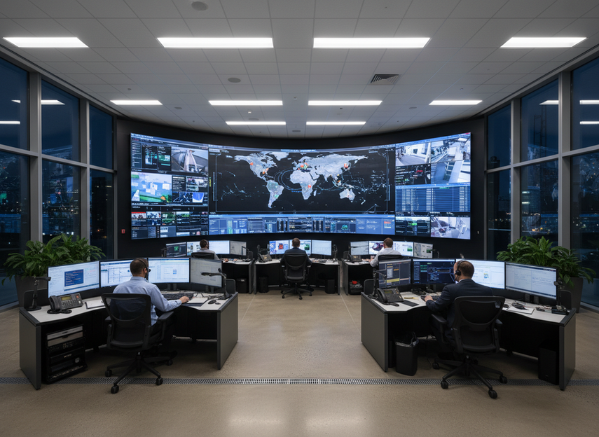
The command center LED wall redundancy architecture should start with the failure mode that would create the longest or hardest-to-recover outage, not the feature list that sounds most complete. For a 24/7 command center LED wall, that means deciding first whether your biggest risk is power loss, signal-path loss, controller loss, or a localized module failure. In operationally dense rooms, display uptime affects incident response and situational awareness, which is why a mission-critical control room setup needs a clear hierarchy instead of vague redundancy claims.
Start With the Failure Mode
Before you compare hardware, sort the outage types by cost to the room:
- Total power loss, which can black out the wall if the upstream path is not separated well enough.
- Signal chain loss, which can take the wall out even when power is still available.
- Controller loss, which matters when one processor or sender is a single point of failure.
- Module-level damage, which may not stop the whole wall but can still create a serious operator blind spot.
The useful test is simple: if a failure would only create temporary visual degradation, it is not the same as a full-wall outage. That distinction matters because the right LED wall redundancy architecture depends on whether the room can absorb a short interruption or whether a single fault would disrupt response. In a whole-system control-room plan, the wall is part of the operating environment, not a standalone screen.

A good decision sentence to keep in mind is: if one failure path can take the wall offline by itself, protect that path before you add deeper service features. If the room can tolerate brief disruption but not long recovery, the next layer should improve switchover speed rather than chase every possible backup path. Operational intelligence in 24/7 rooms depends on that kind of prioritization.
Match the Redundancy Layer to the Risk
The main choice is not whether redundancy exists, but which layer it protects first. In practice, power, signal, controller, and serviceability each solve a different problem. 2N versus N+1 power is a useful shorthand here: 2N is deeper infrastructure protection, while N+1 is more limited and usually covers individual component failure inside one system.
Dual Power Redundancy
Dual power is the floor when the dominant risk is feed failure, UPS failure, or a local distribution issue that would otherwise black out the wall. It makes the most sense when the room has independent power paths and the rest of the AV chain is already designed to avoid a single common dependency. On its own, though, dual power is not a complete answer to controller or signal faults. A room can have redundant power and still lose the wall if the display path has a single point of failure.
That is why the power decision should be read as a stop-or-escalate rule. If the room’s biggest concern is infrastructure loss, start with power depth. If a single cable, sender, or processing fault would still stop operations, escalate beyond power.
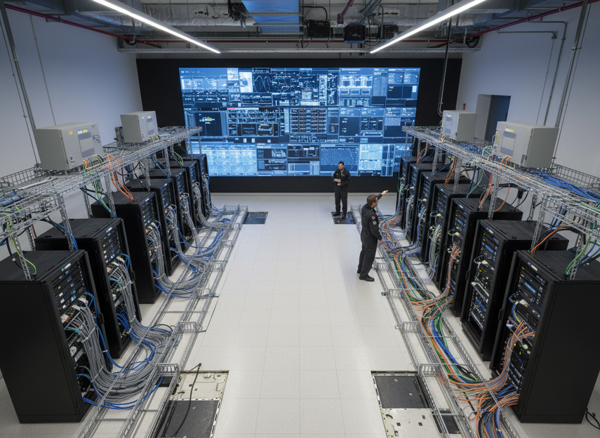
Signal and Controller Failover
Signal redundancy protects a different failure path than power. A closed-loop or loop redundancy design can maintain operation if a single cable fails by rerouting data through an alternate path, which is why it is useful for signal failover with loop redundancy. That does not mean every wall needs the same level of controller protection, but it does mean controller-path risk should be treated separately from power-path risk.
For command center LED wall failover, the key question is whether the display can keep working when the sender, processor, or one cable path drops out. If the answer is no, dual power alone is not enough. If the room can live with manual recovery for a short period, then the added complexity of automatic signal failover may be more than it needs. If it cannot, signal and controller protection move up the list quickly.
Module-Level Protection and Serviceability
Module-level protection is best viewed as recovery-speed planning, not outage prevention. Hot-swap or front-service access reduces the time a localized problem stays visible, but it does not replace power or signal redundancy. In other words, it helps you repair faster after a fault; it does not stop every fault from happening.
That matters in rooms where maintenance windows are tight or where operators cannot lose the whole wall just because one section needs service. For mission-critical display redundancy planning, service access, spare parts, and on-site switchover procedures should be checked before procurement, because a wall that is hard to reach can turn a small fault into a long disruption. AVIXA cable-management guidance is a good reminder that protected signal routing and maintainable installation practices belong in the same conversation.
Here is the practical judgment: if a localized failure can be serviced quickly without interrupting the room, module-level protection is a strong convenience and recovery feature. If a localized failure would force a long outage, serviceability should be treated as part of the redundancy scope, not an afterthought.
A Practical Layer-By-Layer Decision Matrix
| Room Type | First Layer To Protect | Add This Next If Needed | What Not To Overbuy |
|---|---|---|---|
| Standard operations room | Basic power protection | Faster service access | Deep controller redundancy that does not reduce the room’s real risk |
| Multi-shift security operations room | Dual power | Signal-path protection if one cable or sender fault would disrupt monitoring | Full-stack redundancy when the room can accept a short maintenance window |
| Retrofit control room | The most likely outage path in the existing layout | Protected routing or service access where access is constrained | A new-build redundancy plan that ignores fixed cabling and access limits |
| 24/7 emergency operations room | Dual power plus the most failure-prone display path | Signal/controller failover and serviceable modules if the failure cost is high enough | Treating module-level convenience as a substitute for path redundancy |
The point of the matrix is not to declare one universal winner. It is to show when the recommendation flips. A room that can live with a short service window may not need every layer. A room that cannot absorb a single-path fault should escalate sooner, especially when the minimum viable stack needs to match the room’s outage cost rather than the budget headline.
For retrofit projects, the practical answer often changes because access and distribution are already fixed. In those rooms, redundancy depth is less about theoretical best practice and more about what can actually be maintained, tested, and serviced without creating a bigger outage than the one you are trying to avoid.
Use Room Criticality to Set Depth
A useful way to size LED wall redundancy architecture is to match the minimum stack to the room’s tolerance for interruption. The matrix above helps show the pattern: as criticality rises, the acceptable floor moves from simple protection toward a deeper stack that includes power, signal, and controller layers.
The point is not to buy the deepest stack everywhere. It is to match the room’s real failure cost. A standard operations room may only need faster recovery and basic power protection. A 24/7 emergency operations room may need dual power, signal failover, and serviceable modules because a long interruption is not acceptable.
For retrofit rooms, the answer often changes because access and distribution are already fixed. If the room cannot be reworked easily, the right design is the one that can be maintained and tested without creating a bigger outage than the one you are trying to avoid.
Build the Minimum Viable Stack
When you scope a 24/7 command center LED wall, write the redundancy plan in this order:
- Identify the most expensive outage first. If a power-path blackout is the worst case, start there.
- Separate power, signal, controller, and serviceability into different decisions. Do not let one layer stand in for the others.
- Confirm the dependencies. Check distribution, switching, cable routing, and access before hardware is finalized.
- Define acceptable visible downtime. A room that can accept a short visual gap has a different design target than one that cannot.
- Decide on spare parts and recovery steps. A good design without a practical recovery plan still creates downtime.
That sequence keeps mission-critical display redundancy planning focused on the room’s real failure mode instead of on marketing language. It also reduces the common mistake of buying the deepest stack everywhere, even when the room only needs one or two layers to protect the most costly outage.
A practical rule is this: if deeper redundancy does not change the room’s most likely or most expensive failure, it is probably not the next dollar to spend. If it does, move up the stack one layer at a time and stop when the remaining risk is acceptable.
Verify Service Access Before You Commit
Before final approval, check the parts that determine whether redundancy will actually work in the room. You do not need just a drawing; you need a maintainable path.
- Confirm whether the wall allows front service, rear access, or both.
- Verify that service paths stay usable in the real room layout, not only on paper.
- Check that protected signal routing does not conflict with power routing or maintenance access.
- Ask which spare parts should be on site for the chosen redundancy depth.
- Make sure switchover procedures are documented and testable without creating an unplanned outage.
- Reject any proposal that says "redundant" but never names the failure path it protects.
A helpful go/no-go question is whether the proposal protects the room’s most expensive outage first. If it does not, the design is probably missing the right layer or trying to use serviceability as a stand-in for actual failover. For teams comparing options, Chipshow’s command center solutions and mission-critical display paths can be checked as navigation starting points, but the real approval test is still the failure path and the recovery plan.
Final Takeaway
The best LED wall redundancy architecture is the one that protects the room’s most expensive outage first. Start with power, signal, controller, and serviceability as separate layers, then stop when the next layer no longer changes the real risk. If you are planning a 24/7 command center LED wall, use the decision tree above to narrow the stack before you compare hardware. If you want the safest next step, validate your failure path, then confirm access and switchover before you buy.
FAQs
How Do I Decide Between Dual Power and Signal Failover First?
Start with the failure mode that would cause the longest or hardest-to-recover outage. Dual power is usually the first choice when the biggest concern is feed or UPS loss. Signal failover comes first when one cable, sender, or processor fault would still take the wall offline.
What Does Hot-Swap Module Protection Actually Solve?
It mainly shortens recovery time after a localized fault. That can reduce visible downtime and maintenance disruption, but it does not replace power redundancy or signal-path protection. Treat it as a serviceability feature, not a substitute for failover design.
When Is Dual Power Enough for a Command Center LED Wall?
Dual power can be enough when the room’s main risk is infrastructure power loss and the rest of the display path can tolerate brief manual recovery. It becomes less sufficient when a single signal or controller fault would create a major operational gap.
Can a Retrofit Use the Same Redundancy Logic as a New Build?
The logic is similar, but the answer often changes because retrofit rooms already have fixed access paths, cabling routes, and distribution. That can make serviceability and protected routing more important than they would be in a new build.
Why Should the Decision Tree Start With Failure Modes Instead of Product Features?
Because features can look redundant while still sharing a common point of failure. Failure-mode-first planning helps teams compare proposals on the same basis and avoid paying for layers that do not reduce the room’s real outage risk.